


The mechanical centrifugal switch has simple structure, convenient installation and high cost performance, and is widely used in various single-phase motors on the market. In order to meet the needs of higher-end motors, our company has developed a non-contact electronic centrifugal switch to help the motor from starting, running, and stable transition to rated speed.
This product adopts a method of induction coil and induction rotor magnetic field. The signal is picked up by the induction coil and Hall, and the low-pass filter is limited to amplify, shape, and cooperate with the microchip single-chip microcomputer to model the motor, and extract the speed of the rotor. , When the microchip judges that the motor speed has risen to the set switching speed, after making a millisecond-level judgment, the non-contact SCR method is used to disconnect the starting capacitor to complete the motor start.
Features
1. A microchip electronic centrifugal switch, which completely overcomes the defects of the current mechanical switch starting motor used in the market.
2. Speed judgment is fast, about 180M---300MS to complete speed detection.
3. The switching speed can be adjusted by software, which is convenient and efficient, while the adjustment of mechanical switches is not accurate and the range is narrow.
4. When the motor starts to run smoothly, the transition is smooth and there is no chattering phenomenon. During the running process, when the load suddenly increases, it can judge by itself whether to add the starting capacitor to avoid the hidden danger of the motor being burned out due to overload. .
5. Non-contact switching, no sparks will be generated during switching, sintered contacts and fires will occur in the presence of flammable gas.
6. Compared with the life of mechanical centrifugal switches, the life of electronic centrifugal switches is about 5 times that of mechanical switches and has advantages compared with electronic centrifugal switches in the same industry.
7. Effectively solve the problems of difficult adaptation of high-power electronic electronic centrifugal switches, disturbed startup, and high startup failure rate.
8. Effectively solve the defects of inaccurate opening time of the existing electronic centrifugal switch, insufficient opening torque when the motor is started too fast, or too slow opening, which causes the motor starting current to be too large.
9. Successfully solved the defect that the electronic centrifugal switch cannot be started frequently, and the forward and reverse directions are reversed. It has been widely used in motor and equipment industries such as: water treatment motors and equipment, food machinery, building materials machinery, vacuum pumps, explosion-proof motors, high-pressure cleaners, air compressors, woodworking machinery, oil pumps, water pumps, garbage disposals, medical equipment, Engineering mixers, high-pressure water pumps, and other industrial equipment.
| Specifications of YL type single-phase asynchronous motor electronic starter | ||||
| model | YC- LIH -24A-01 YC- LIF-24A-02 IH-24A-01 IH-24A-02 |
YC- LIH -30A-01 YC- LIF-30A-02 IH-30A-01 IH-30A-02 |
YC- LIH -40A-01 YC- LIF 40A-02 IH-40A-01 IH- 40A-02 |
YC- LIH -60A-01 YC- LIF-60A-02 IH-60A-01 1H-60A-02 |
| Applicable power (KW) | 0.75以下 | 0.75-1.5 | 1.5-2.2 | 2.5-5.0 |
| Speed detection method | LIH:Magnetic field LIF:frequency IH:vector |
Power frequency:50Hz/60Hz | range of rotation:1300-3600r/m | |
Installation Notes
(1) Parameter configuration: According to the parameters of the motor, configure the parameters of this product by short-circuiting the pin header with the jumper cap. The pin position is shown in Figure 1, and the detailed settings are shown in the table below.
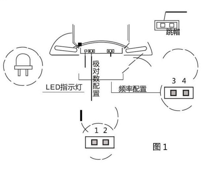
Note: The jumper cap must be inserted into the bottom of the pin header and fixed with 704 silicone rubber after configuration.
| Motor configuration table | |||
| Pole pair frequency | 50Hz | 60Hz | |
| Rated speed: |
P=1 2700-3600r/m |
1、2open circuit 3、4open circuit |
1、2open circuit 3、5open circuit |
| Rated speed: |
P=2 1300~1800r/m |
1、2open circuit 3、5open circuit |
1、2open circuit 3、6open circuit |
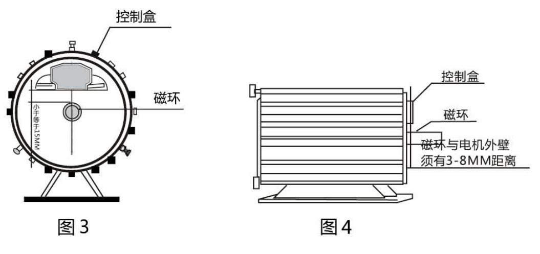
(2) Remove the motor fan blade cover and fan blade, then install the control box, and tighten the screws (diameter 4mmx10mm). After installing the control box, insert the magnetic ring provided by the product according to the outer diameter of the motor shaft, and then tighten the screws, see Figure 2

NOTE: The control box ears must fit snugly against the outer wall of the motor. The magnetic ring must be directly under the control box, and the distance between the center of the lower arc of the control box and the outer diameter of the magnetic ring must be less than or equal to 15MM, and the magnetic ring must be kept 3~8MM away from the outer wall of the motor. See Figure 3 and Figure 4.
(4) Wiring: see Figure 5 for the wiring diagram
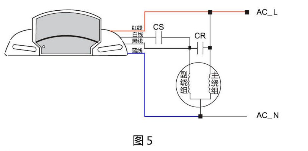
Description: The red wire/blue wire is connected to the motor power supply.
The white wire is connected to one end of CS (startup capacitor).
The black wire is connected to the common terminal of the secondary winding, CR (running capacitor) and CS (starting capacitor).
Note: The 4 outgoing wires of the control box must have a certain distance from the fan blades to prevent the wires from colliding with the fan blades when the motor rotates and causing failure.
(5)After the installation is complete, install the fan blades and fan blade cover back to their original positions。
| Simple Troubleshooting Instructions | ||
| Phenomenon | state | illustrate |
| Red LED light on | Indicates that the start capacitor is working when the motor starts | |
| Green LED lights up | Indicates that the starting capacitor has been cut off and the motor has started normally. | |
| yellow light at work | After the motor is started or when the start time is longer than 4 seconds, the yellow light will be on, and it will turn off after about 7 seconds of charging, and the light will be on again. | This is due to the negative cutting of the motor during operation, the speed is lower than 70% of the fixed speed, and the starting capacitor is added to the work. Eagle appears in Europe normally, not a malfunction. |
| When starting or working, the red light is on for 4 seconds, then the red light is off, then the yellow light is on for 7 seconds, then off, and the red light is on again. | There are several reasons as follows: (1) The load of the belt is greater than the rated load of the motor. | It means that the motor does not match the load it carries, and generally the load is about 60% of the rated power of the motor. |
| (2) The motor startup turtle capacity is damaged or the capacity is reduced. Capacitors have three important parameters, withstand voltage, capacity debt, and the tangent of the damage wash angle is 01 (D). | It means that even if the starting capacitor capacity remains unchanged, if the value of (D) increases, the motor cannot start normally. Solution: Replace the starting capacitor. | |
| (3) The motor winding is open or partially short-circuited. | The motor should be replaced or repaired at this time | |
| (4) The motor shaft is damaged, causing the motor to stall or pre-movement is not smooth. | Overhaul or replace the motor | |
| (5) If it is not a problem of 1~4, it may be the damage of electronic switch circuit components or Weibo. | Replace the electronic switch or break the ring. | |
Precautions
(1) This product is used to help the motor start.
(2) When the motor cannot start or work normally, the power supply should be turned off immediately to eliminate the fault, and then it can continue to be used; it is strictly forbidden to forcibly turn it on, otherwise it will
lead to more serious failures and even fires.
(3) A matching air switch must be used between the power supply and the motor.
Keyword:
电子
电机
启动
开关
电容
开路
离心
yc-
速度
Similar products
Refrigeration controller
Refrigeration controller
Refrigeration controller
Refrigeration controller
Leave us a message
ADD:
4th Floor, No. 268, Jincheng Road, Jiaochuan Street, Zhenhai District, Ningbo City, Zhejiang Province
TEL:
EMAIL:
FAX:
[ Add WeChat ]


